ET CO2 Module measures carbon dioxide (Capnography) and respiratory rate with a unique solid-State sensor called a Capnostat. The Capnostat placed onto an Airway Adapter placed in the patient’s airway circuit typically between the ventilator elbow and the patient end. Capnogram measure of exhaled CO2 in the form of capnography waveform for capnographic purpose
In the economically mainstream capnography technology helps for an accurate measurement.
Capnographic Principle of Operation
Infrared light generated on one leg of the “U” shaped sensor. IR rays beamed through the windows of the airway adapter to a detector in the other leg of the sensor. Carbon dioxide, flowing in the airway adapter as a result of respiration, absorbs some of this light energy.
The monitor relates the amount of detected energy to the amount of CO2 in the sample cell (the airway adapter). This results in a Capnogram display and numerical values for capnographic values and respiration rate.
Uses of an adaptive digital detection algorithm system. Highly accurate digital filters and adaptive thresholds to cover a wide range of monitoring situations including,
Rebreathing,
Neonatal respiration rates and capnographic ET CO2 levels.
Used widely in OR/OT and ICU conditions without the operator having to change monitor settings.
Measuring Respiration Rate
Respiration calculated by measuring the time interval between detected peaks of the capnography waveform. The inverse of this measurement displayed as respiratory rate certain rebreathing circuits or the presence of the artifact. Cardiogenic oscillations may cause the monitor to react to non-respiratory CO2 fluctuations in the form of numerical displays.
The Capnogram display continues to provide an accurate picture of the CO2 waveform.
A Respiratory Rate Editor can be enabled to make the instruments more selective in its differentiation of waveforms caused by breathing. The monitor will adapt slowly to sudden changes in the respiratory rate.
Capnography waveform
CO2 waveform reflects various stages in breathing. Capnograph or capnogram is an important diagnostic tool because its shape is virtually identical in all basically healthy people.
End-tidal CO2 is the concentration of ETCO2 capnographic measured at the end of tidal volume expired (Point D in the above diagram).
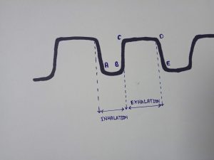
A-B The baseline, that is the level of minimum CO2 concentration, observed immediately after inspiration.
B-C The expiration phase of the respiration cycle.
C-D The expiratory plateau, that is the period during which the level of CO2 in the lungs ceases to increase significantly.
D The end-tidal concentration point, at the end of the expiration phase, at which EtCO2 measured.
D-E The onset of the inspiration phase of the respiration cycle.
The production, transportation, and elimination of CO2
Understanding of Capnometry
CO2 produced by all the cells in all the tissues in the body as a by-product of metabolism. From the cell, CO2 diffuses into capillary blood, from where CO2 transported into the venous circulation. During contraction of the heart, venous blood is pumped through the pulmonary circulation to the lungs for gas exchange. Lungs made up of millions of alveoli, which permits easy gas diffusion from pulmonary blood to alveolar gas space.
Continuous breathing CO2 diffuses keeps CO2 concentration in alveoli lower than that in the pulmonary circulation. During exhalation, the gas leaving lungs mixes thoroughly, so Capnograph measures the average concentration of CO2 from all the alveoli.
Arterial to alveolar difference of C02.
Although end-tidal CO2 closely follows the blood CO2 level, they are not exactly the same.
Normally, the arterial blood CO2 level (PaCO2) is higher by 3-4 mmHg. than the alveolar CO2 (PACO2).
The ETCO2 is due to a mismatch of ventilation and perfusion of the alveoli in the lungs. (Even in healthy patients, there some parts of the lungs not perfused as well as ventilated).
Capnography gives an excellent picture of the respiratory process.
In such cases when the patient exhales CO2 gas from the unperfused part of the lungs, it dilutes the CO2 rich alveolar gas coming from the rest of the lungs. This lowers the EtCO2 and hence EtCO2 increases known as alveolar dead space ventilation.
Arterial blood CO2: PaCO2
Alveolar CO2: PACO2 Arterial to alveolar difference aADCO2 which is normally 3-4 mmHg.
Patient Preparation:
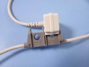
The adult Airway Adapter used when monitoring patients with Endotracheal Tube diameters greater than 4.0 mm. Alternatively, the Disposable Adult Airway Adapter may be used.
1. Verify the windows are clean and dry.
Clean or replace the adapter if necessary.
Snap the airway adapter into the Capnostat to get Capnogram
Align the arrow on the bottom of the airway adapter with the arrow on the bottom of the Capnostat. Press the sensor and airway adapter together until they “Click” sound comes
If necessary, perform an adapter calibration. Otherwise, skip this step
Adapter Calibration needs to performed each time you switch from using an Adult to a Neonatal adapter, but not if you switch from an Adult adapter to another Adult adapter. Calibration performed in the monitor before displays
ADAPTER CAL To perform an Adapter calibration:
3a. Select CO2 CAL in SETUP of capnography.
3b. Place the sensor and airway adapter away from all sources of CO2 (including the patient’s and your own exhaled breath, and ventilator exhaust valves.)
Select adapter CAL. After this get the capnographic representation on screen
Read more about the Tracheostomy
Note
If the monitor detects changing ET CO2 levels (breaths) during an adapter calibration, Breaths detected displayed followed by a place on the adapter in the air. To continue remove the source of CO2 wait 30 seconds, and press Adapter cal.
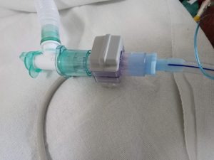
When using the AdultAirway Adapter, place the Capnostat/Airway Adapter assembly at the proximal end of the circuit between the elbow and the ventilator circuit wye.
Caution
For optimal results, do not place the airway adapter the ET tube and the elbow, to avoid patient secretions to block the adapter windows. Position the Airway Adapter with its windows in a vertical and not a horizontal position. This helps keep patient secretions from “pooling” on the windows. To prevent “rain-out” and moisture from draining onto the Airway Adapter.
Do not place the Airway Adapter in a gravity-dependent position.
Check that the connections correctly by verifying a proper Capnometry
waveform (Capnogram) on the monitor display.
The sensor cable should face away from the patient.
To secure the sensor cable safely out of the way, attach Sensor Cable Holding Clips to the airway tubing, along with sensor cable.